If you’ve ever stood next to an industrial power cabinet watching meters flicker, or helped a small business troubleshoot why their energy bill spiked unexpectedly, chances are a current transformer (CT) was quietly making that visibility possible. For 12 years, I’ve run a small CT supply company—we don’t do one-size-fits-all parts; every unit we ship is designed for a specific customer’s application. Early on, I made the mistake of pulling a generic CT from our stock and sending it to a client who needed one for a saltwater desalination plant. That CT lasted 72 hours before corroding and melting; the client lost $18,000 in production downtime that week. After that, I stopped selling pre-built units and focused on walking each customer through how we design a CT for their exact needs. If you’re an engineer, plant manager, or electrical contractor who’s ever stared at a CT spec sheet and wondered why “rated current” isn’t enough, this is for you. Current Transformer
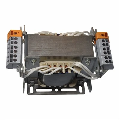
Let’s start with the basics: a current transformer doesn’t step down voltage like a regular transformer—it steps down alternating current (AC) from high line levels (think hundreds or thousands of amps) to a standardized, safe low level (usually 5A or 1A) that meters, relays, and monitoring devices can read. Designing one isn’t just picking a core size; it’s matching the CT’s electrical, mechanical, and environmental specs to what your application will throw at it. The first question every customer asks is, “What’s the primary current?” That’s the easiest one, but most folks don’t realize it’s not just the normal running current. If you’re designing a CT for a manufacturing motor, you need to account for startup inrush current—5 to 7 times the rated current for 10 to 20 seconds. Pick a CT with a primary current rating too low, and the core will saturate during startup, giving a false low reading that makes you think the motor is underloaded. We recently designed a CT for a 500HP ball mill that has a normal running current of 300A, but startup inrush hits 1,800A. We specified a 500A primary CT with a class 10P20 rating—meaning it can handle 20 times the rated current for 10% error, which is exactly what that mill needed to avoid tripping false fault alerts.
Next, there’s the secondary current. This is the standard output for your metering or protection gear. Most applications use 5A secondary, but if you’re working with long cable runs (like a solar farm that’s 500 feet from the main substation), 5A can cause voltage drop in the wiring, leading to inaccurate readings. We had a solar client last year whose 5A CT setup was giving a 3% error because of 400 feet of 14AWG copper wire. We swapped it to a 1A secondary CT, which reduced the current in the line by 80% and cut voltage drop to 0.15%—fixing their issue without rewiring the entire site. That’s a common mistake: not matching secondary current to your cable length and device sensitivity.
Once the electrical basics are clear, we move to the core material. This is where a lot of new designers cut corners, but it’s non-negotiable for accurate readings. The two most common core materials are silicon steel and nanocrystalline. Silicon steel is cheap and works great for low-frequency applications (50/60Hz, which is standard for most grids), but it saturates easily at high currents. Nanocrystalline cores, on the other hand, have a much lower saturation point, making them ideal for high-inrush or high-frequency applications like variable frequency drives (VFDs) or EV charging stations. We had a food processing plant that was installing 10 VFDs for new packaging lines. Their original CTs with silicon steel cores were showing 15% error on the VFD outputs because of the high-frequency harmonics. We swapped them to nanocrystalline core CTs, which reduced error to less than 0.5%—critical for their energy management system to track line losses correctly.
Then there’s the burden. Burden is the total load on the CT’s secondary circuit, measured in volt-amperes (VA). If the burden is too high, the CT’s output will be lower than it should be, leading to under-measurement. The burden includes the CT’s own internal resistance, the meter or relay’s internal resistance, and the resistance of the secondary wiring. For example, a power meter with a 0.2VA burden, a 50-foot wire with 0.1VA resistance, plus the CT’s 0.1VA internal resistance gives a total burden of 0.4VA. If we design a CT rated for a minimum burden of 0.5VA, that works perfectly. If we picked one rated for 0.3VA, it would struggle and give bad readings. We always calculate the burden for every customer, and we include a 20% safety factor to account for future additions—like adding a new meter to the line a year down the road. That’s a step most small engineers skip, and it leads to avoidable callbacks.
Mechanical design is next, and it’s just as important as electrical specs. A CT installed outdoors in a wet climate needs to be sealed against dust and water, with an NEMA 4X rating. A CT installed inside a switchgear cabinet needs to fit through a 3-inch knockout hole, or mount directly to a busbar. We had a utility client who ordered 20 CTs for a substation upgrade, and their team forgot to check the busbar size—they ordered 4-inch window CTs for 6-inch busbars, which meant they had to wait 3 weeks for custom modifications, costing them $22,000 in labor delays. Now, the first thing we ask for mechanical specs is busbar or cable size, installation space, and any vibration or temperature extremes. For offshore wind farms, we design CTs with reinforced epoxy casings that can handle constant salt spray, minus 40°F temperatures, and 1G of vibration from turbine rotation. On the flip side, for a tiny residential solar inverter, we design compact split-core CTs that snap around the main feed without shutting down the system during installation—something we couldn’t do 10 years ago when CTs required disconnecting the line to install.
Environmental conditions are often the most overlooked factor. If you’re designing a CT for a steel mill, where temperatures can hit 120°F near the furnaces, standard CTs will degrade quickly—their insulation will crack, and the core will lose accuracy. For those applications, we use high-temperature insulation rated for 180°F or higher, and we test every CT at 150°F for 72 hours before shipping. For mining applications, CTs are exposed to coal dust and heavy vibration, so we use dust-tight seals and stainless steel hardware to prevent corrosion. We had a mining client in Western Australia whose original CTs failed every 6 months due to dust ingress; after we redesigned them with double O-rings and a sealed core, they’ve been running for 3 years without a single failure. That’s the kind of problem-solving that generic CTs can’t handle.
Accuracy class is the final piece of the puzzle, and it’s dictated by what you’re using the CT for. For energy metering, you need a class 0.5 or class 0.2 CT—meaning the error is less than 0.5% or 0.2% of the rated current. For protection relays, you need a higher class, like class 10P or PR, which can handle high fault currents without saturating, so the relay can trip the circuit before damage occurs. We recently designed a CT for a data center backup generator: they needed class 0.2 for billing accuracy, and class 10P for fault protection during a grid outage. We built a dual-purpose CT that meets both specs, which saved them from having to install two separate units—cutting their installation time in half and reducing their costs by 15%.
Let’s walk through a real example to tie this all together. A client in the paper pulp industry came to us needing a CT for their main power feed to a recovery boiler. Here’s what they told us: normal running current is 1,200A, startup current hits 4,500A (3.75x rated), secondary current is 5A, burden is 1.2VA (from two meters and 60 feet of wire), the CT will be installed outdoors in a humid, polluted area with temperatures ranging from -10°F to 110°F, and it needs to fit around a 5-inch square busbar. We went through each step: primary current is 1,500A (we added a 25% safety factor above their 1,200A to avoid overload during demand spikes), secondary current is 5A, core material is silicon steel (no high harmonics here, so it’s cheaper than nanocrystalline), burden is 1.44VA (added 20% safety factor, so we spec’d a CT rated for 1.5VA minimum), mechanical specs: 5-inch window, NEMA 4X seal, stainless steel hardware, accuracy class 0.5 for metering and 5P20 for protection (can handle 20x rated current with 5% error for the relay). We tested the CT at our in-house lab: ran it at 4,500A for 15 minutes, checked the accuracy at both running and fault current, tested it in a salt spray chamber for 1,000 hours, and verified it fits their busbar. That CT has been running for 2 years now, and the client hasn’t had a single issue with accuracy or durability.
If you’re designing a CT for a specific application, don’t just rely on off-the-shelf parts. Too many engineers cut corners here, leading to downtime, inaccurate readings, or costly replacements. The key steps are: define your primary current (including inrush and demand spikes), match secondary current to your wiring length, calculate the total burden, select the right core material, account for mechanical and environmental conditions, and pick the accuracy class for your use case. If you skip even one of these steps, you’re setting yourself up for problems down the line.
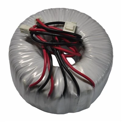
At our company, we don’t just sell CTs—we work with you through every step of the design process. We’ve built thousands of custom CTs for applications from EV charging stations to offshore wind farms to small businesses adding solar panels. If you’re working on a project and need a CT that’s tailored to your exact needs, feel free to reach out to our team to discuss your requirements and get a custom design quote.
High Frequency Transformer References:
- Electrical Construction Maintenance. (2021). “Current Transformer Selection Guide: Key Specs to Consider for Proper Application.”
- IEEE Standard C57.13-2021, “Standard Requirements for Instrument Transformers.”
- Cooper, W. (2019). “Current Transformer Core Materials: Matching to Application Needs.” Power Engineering Magazine.
- National Electrical Manufacturers Association (NEMA). (2020). “Standard for Enclosures for Electrical Equipment (NEMA 250).”
Dongguan Hensiron Electric Co., Ltd.
As one of the most professional current transformer suppliers in China, we have world-leading production equipment and strong manufacturing capabilities. Please feel free to buy high quality current transformer made in China here from our factory. Customized orders are welcome.
Address: Building 4, Xinxing Industrial Zone, Wangao Road, Wanjiang Street, Dongguan City, China
E-mail: jessica@dghensiron.com
WebSite: https://www.dghensiron.com/
